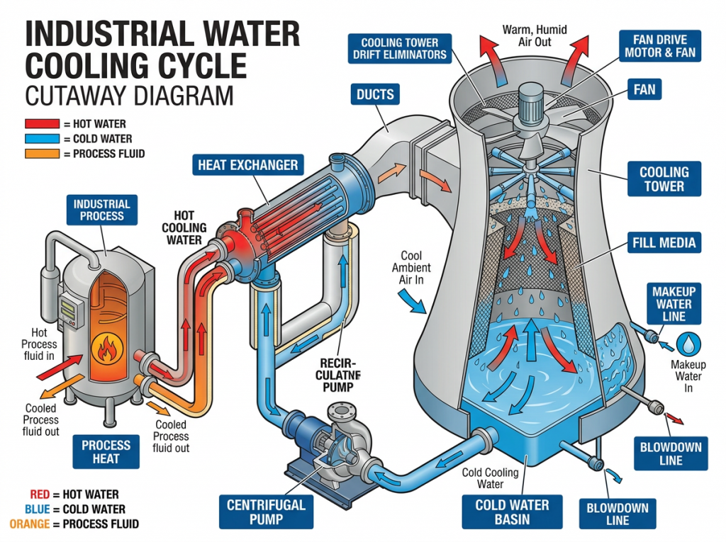
Diagram showing the flow and components of an industrial water cooling cycle
This detailed cutaway diagram illustrates an industrial water cooling cycle, highlighting major components and water flow directions. The system starts with hot process fluid entering the industrial process vessel, transferring heat to the cooling water via a heat exchanger. Hot cooling water is pumped through the heat exchanger, where it cools down before entering the cooling tower. The cooling tower circulates water using a fan and motor, where ambient air cools the water through evaporation across fill media. Cold water collects in the basin and cycles back to the system via a centrifugal pump. Supplementary lines include the makeup water line adding fresh water and blowdown lines removing excess water. Red arrows indicate hot water flow, blue arrows indicate cold water flow, and orange arrows indicate process fluid flow.